Remote monitoring
SECONDARY SUBSTATIONS REMOTE CONTROL AND MONITORING DEVICE
In compliance with Enel GSTR001/1 e GSTR001/2
The UP2015-UP8 is remote control Peripheral Unit for secondary substations and Medium Voltage (MV) power distribution system
Main functions of the UP2015-UP8 are:
- Remote control and Automation of Secondary substation switchgear
- Permanent Fault detection
- Monitoring of Medium Voltage Power Grid
The UP2015-UP8 allows to create the comunication system between field and The Distribution Control Centre. In particular:
- Receiving and carrying out commands sent by the Distribution Control Centre (Remote Control).
- Send field collected informations (remote signaling and telemetry) to the Distribution Control Centre side
These functions allow to guarantee Reliability Hight Level of Electric Power Distribution system, reducing the number and duration of power outages caused by circuit faults.
Furthermore, Remote Control permits optimization of electric power distribution system maintenance and planning policies.
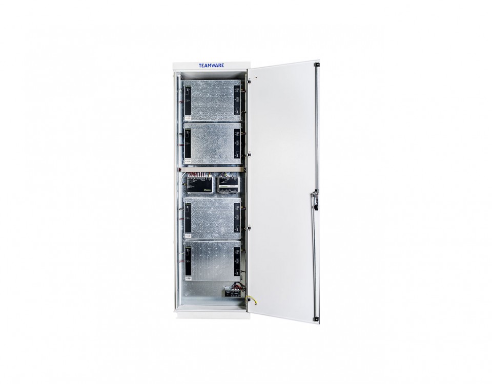
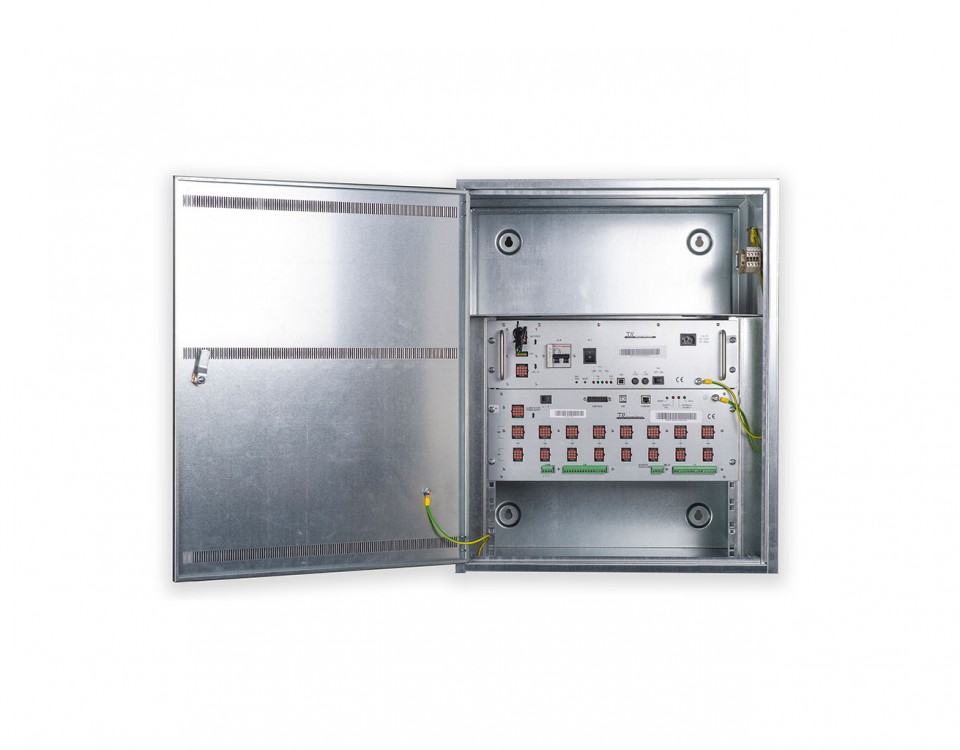
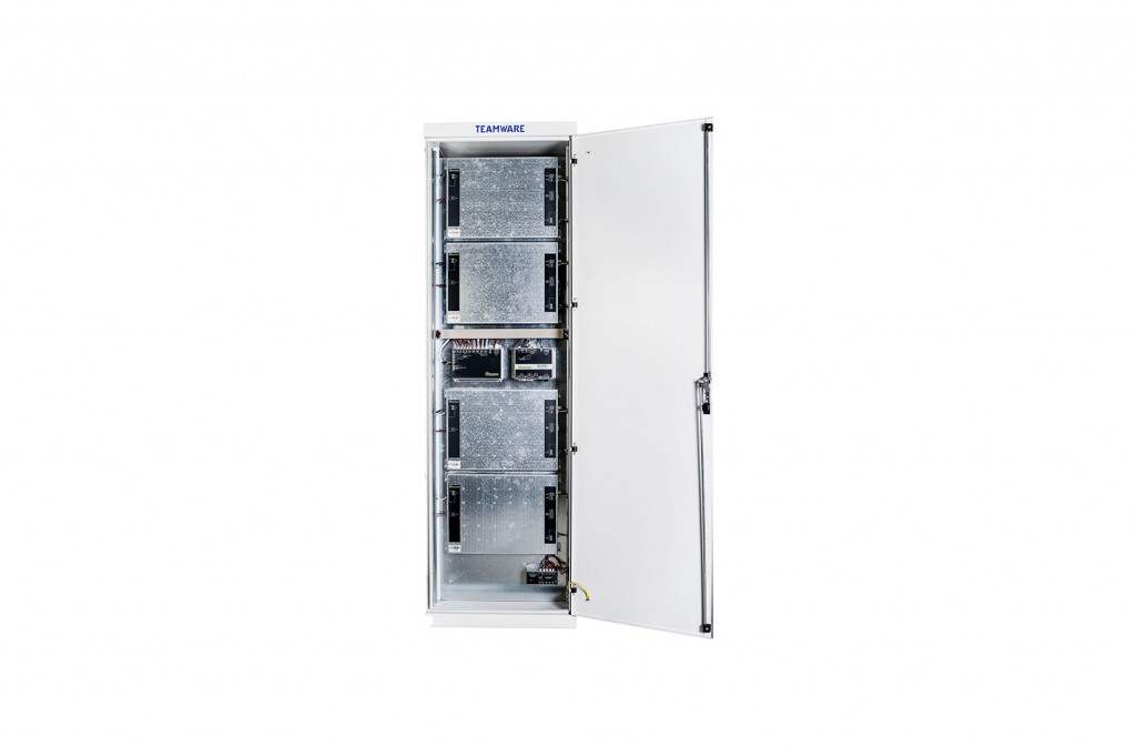
The UP2015-UP8 is made by two components integrated in a metal cabinet:
- The UE8 module: is the unit of data acquisition, monitoring, transmission, and processing. The UE8 is the field interface also. The UE8 is completely remote programmable by personal computer.
- The ACB module: includes a power supply and a battery system with charger circuit . The ACB supplies the power to UE8, to comunication device called DCE and to motors of Switchgear connected to the UP. The Battery system is made by two Lead-acid battery and the ACB monitors his functional states. The DCE is completely programmable from personal computer by local comunication port.
Main features
Extensive range regarding Remote Control of Electric Power Distribution System features.
Acquisition, processing and collection of the Switchgear states.
Managing of fault-detection automation
Archiving of electric power distribution system data management and of chronological events (fault, tension failure, exc) trend.
Processing of field signals correlation for generating signs to the Distribution Control Centre.
Validation and dispatch of commands from the the Distribution Control Centre to Switchgear.
Comunication with the Distribution Control Centre technologies:
- GSM/GPRS/UMTS
- Public Switched Telephone Network (PSTN)
- Network LAN/WAN IP based
Comunication Protocols:
- IEC 60870-5-101
- IEC 60870-5-104
Management of diagnostic of failure devices with emission of local and remote warnings
Monitoring of Secondary Substation temperature throuth dedicated sensor and managing of door opening warning.
Power supply to the automation components of secondary substation.
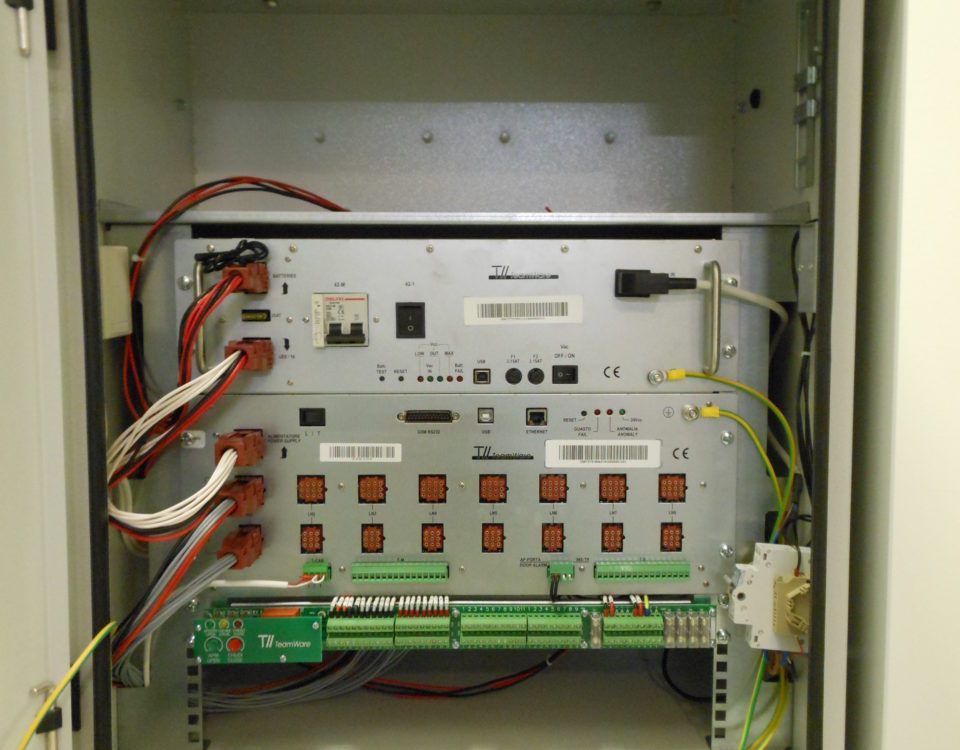
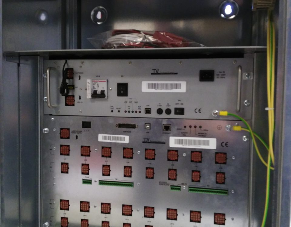
The UE8 Module
Input/output Interface
49 Remote signals (TS):
- galvanically optocoupled digital input
- sampling: 10msec
16 Remote commands (TC):
- Relay output with 1 / N of the uniqueness control of the carring out, execution policy in double safety and evaluation of the value of the output load impedance.
- nominal current : 5A
- interruption rate: 0,5A a 110 Vcc con L/R = 40msec.
8 Telemetry (TM):
- differential analog inputs galvanically isolated
- input impedance: 50ohm
- measure range: ± 5mA e 4-20mA
- precision: 1%FS
- resolution: 12bit
8 Digital Outputs (UD):
- open collector (source) output galvanically isolated (max current 50mA)
Communication ports
There are three comunication ports:
- 1 Ethernet Port 10/100BaseT (available both as LAN/WAN interface and as configuration and local monitoring port)
- 1 serial Port V.24 (interface to external DCE device dedicated)
- 1 USB 2.0 device Port (configuration and local monitoring dedicated)
Power Supply
The UE8 module is powered by the main source with:
- Nominal voltage: 24Vcc ±20%
The Hardware is powered by the secondary source galvanically isolated from the main.
Visual indicators
There are three leds signs:
- Fatal failure
- General anomaly
- Main source presence
Connections
- Ethernet interface: RJ45 connector
- V.24 serial interface: DB25 connector with male poles
- USB local interface: B type connector
- 8 female connectors with 9 poles for connections to RG device
- 8 female connectors with 12 poles for connections to Switchgear
- 1 female connector with 12 pole for connections to the ACB module
- 1 extractable terminal board with 16 poles for connections to remote signals (TS)
- 1 extractable terminal board with 16 poles for connections to Telemetry
- 1 extractable terminal with 4 poles for connections to temperature sensor of the substation
- 1 extractable terminal with 4 poles for connections to particular remote signals :
- Door Opening
- IMS TR Opening
Mechanical features
The modules are contained in a standard rack box 19” 4U
The ACB Module
Main electric features are:
Main source voltage: 100/230 VAC (-10%÷+20%), setting up by dedicated selector.
Nominal frequency: 50/60Hz
Power: 150W
The secondary power sources are:
Output of battery charger and load powered:
- Nominal Voltage: 24VDC set between 23 and 28 VDC balanced also in function of the battery temperature
- Maximum available current (fixed): 5A ±5%
Auxiliary output if power supply:
- Nominal Tension: 12 VDC
- Maximum available current (fixed): 1A
Whole efficiency:
≥75% ± 3%
(calculated at maximum supplied current 5A and at nominal voltage of 24VDC)
Visual indicators
There are five leds signs:
- Main source presence
- Secondary source presence
- Secondary tension low level
- Secondary tension maximum level
- Battery failure
Connection and optionals
- USB local interface: type B connector
- 1 female connector with 9 poles for connection to batteries and external modem
- 1 female connector with 12 poles for connection to verso the UE8 module
- 1 three-poles socket for the main power supply
- 1 bipolar circuit breaker for IO: 2A type loads
- 1 Thermal magnetic circuit breaker with auxiliary contact: 20A C curve
- 2 fuse holders with fuses of main grid protection: 3,15AT.
- 1 fuse holder with fuse 20AT of battery output protection
Mechanical features
The modules are contained in a standard rack box 19” 3U
EMC
Emissions
- EN55022 Class A
Immunity
- EN61000-4-8: Level 5
- EN61000-4-10: Level 4
- EN61000-4-3: Level 4
- ENV50204: Level 4
- EN61000-4-2: Level 4
- EN61000-4-16: Level 3
- EN61000-4-6: Level 3
- EN61000-4-12: Level 3
- EN61000-4-18: Level 3
- EN61000-4-4: Level 3
- EN61000-4-5: Level 3
Environmental conditions
Operating temperature: -10÷ +55°C
Storage temperature: -25÷ +70°C
Humidity: 93%
IP Grade
EN60529-1 compliant: IP30
Configuration software
UP2015-UP8 is accompanied by a configuration application program that runs under Windows ©. It allows the configuration of the UP both remotely and locally.
Local configuration must be performed with a personal computer, connected to the UP via USB 2.0 or through an Ethernet interface.
The application allows to define:
- The general parameters of operation of the device
- Communication parameters
- The characteristics of the OdMs connected to the UP
- Remote Signals, Remote Measures and the Digital outputs.
Furthermore, it is a useful diagnostic and verification tool, as it allows:
- Monitoring the status of the inputs and outputs
- Monitoring, with the possibility of saving on file, the states of the automatisms, their transitions and the corresponding values assumed by the physical and logical inputs.
- Sending commands to the instantiated OdMs.
It is also possible to analyze the recordings at a later time.
Please download our technical data sheet (also available in Romanian).
Download “UP2015-UP8 datasheet - eng”
Download “UP2015-UP8 datasheet - ro”
- SECONDARY SUBSTATIONS REMOTE CONTROL AND MONITORING DEVICE In compliance with Enel GSTR001/1 e GSTR001/2
- SECONDARY SUBSTATIONS REMOTE CONTROL AND MONITORING DEVICE In compliance with Enel GSTR001/1 and GSTR001/3
- SECONDARY SUBSTATIONS REMOTE CONTROL AND MONITORING DEVICE In compliance with Enel GSTR001/1 e GSTR001/2