Efficienza energetica
A single module for three-phase measurements and electrical panels protection
- GENERAL FEATURES
- SPECIFICATIONS
- OPERATION MODE
- SETUP AND OPERATIVE PARAMETERS PREDISPOSITIONS
- DOWNLOAD AREA
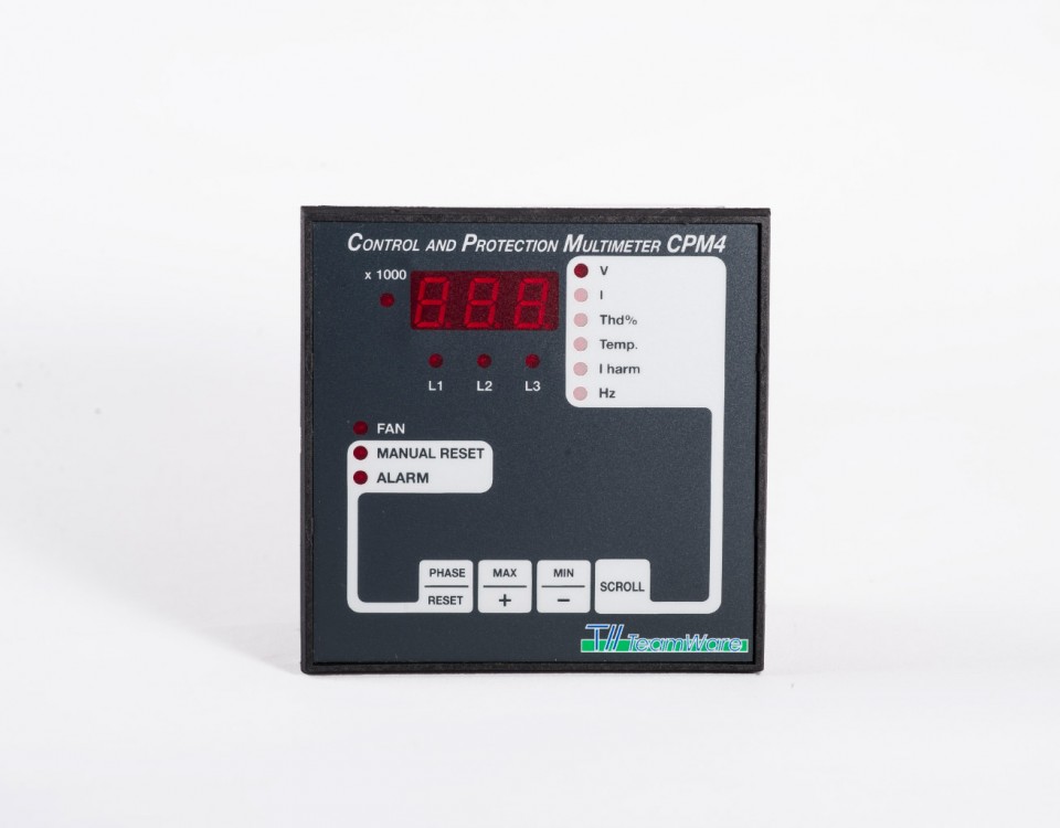
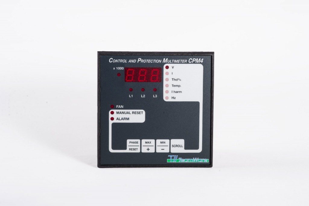
The CPM device has been designed to protect electrical panels and plants, in particular power factor regulation and filtering plants, by mean of continuous monitoring of line voltage, line current (amplitude and harmonics) and temperature.
The voltage value is compared with a threshold value programmable, giving an alarm when exceeded.
Current value is processed to calculate the RMS amplitude and the total harmonic distortion THD: when a maximum short-circuit and current distortion threshold is exceeded, an alarm output is generated.
The temperature value is monitored to activate cooling devices (fan, etc…) when a programmable pre-alarm threshold is exceeded and to produce an alarm if a programmable maximum value is exceeded.
All measurements and alarms are displayed on the front panel display. Working parameters setup is accomplished using 4 functional keys.
Small size (DIN 96×96 mm) and low cost make CPM ideal to use in all industrial and civil electrical plants.
For further information, please download our technical data sheet (DOWNLOAD AREA, left sidebar)
- Power Supply: 115/230/400 Vac (depending on model) ±10%, 50/60 Hz
- Consumption: 4 VA
- Size: 96 x 96 x 60 mm. DIN 43700
- Weight: 450 g
- Voltage input: 3 inputs 400 V ±10% phase to phase, 50/60 Hz
- Voltage input impedance: > 1 MΩ
- Current input: 3 inputs from external CT /5A
- Current overload: 20% permanent
- Current circuit consumption: < 0.25 VA
- Voltage accuracy: ±1% f.s.
- Current accuracy: ±1% f.s.
- Current resolution: 10 mA x CT/5
- Current THD accuracy: ±1% f.s. for Irms > 10% f.s; ±5% f.s. for Irms < 10% f.s
- Temperature accuracy: ±1 oC
- Frequency accuracy: 0.2% f.s.
- Timing accuracy: ±1 sec.
- Cooling device relay contacts: 5 A 250 V NO
- Alarm relays contacts: 5 A 250 V NO and NC
- Wirings: removable terminals
- RS232 Communication: requires specific external adapter
- Working temperature: from 0 oC to +55 oC
- Storage temperature: from -10 oC to +70 oC
- Humidity: 95% uncondensed
For further information, please download our technical data sheet (DOWNLOAD AREA, left sidebar)
- Voltage protection: the input line voltage, measured in true RMS, is compared with the threshold value programmed. If the voltage exceeds the threshold for a time longer than 30 minutes, an alarm is produced (voltage and alarm leds blinking) and the alarm relay is opened.
- Current protection: the input current, measured in true RMS, is compared with the reference value set at 120% of nominal value (the primary current of CT). If the current exceeds the threshold for a time longer than 3 seconds, an alarm is produced (current and alarm leds blinking) and the alarm relay is opened.
- THD protection: the current signal is processed to extract the total distortion value. Such value is compared with the programmed threshold: if the THD value exceeds the actual threshold (THD% High Current Threshold or THD% Low Current Threshold) for a time longer than programmed, an alarm is produced (THD and alarm leds blinking) and the alarm relay is opened
- Temperature protection: temperature value is compared with the temperature threshold programmed: if the temperature value exceeds the threshold for a time longer than 10 seconds, the FAN led is lighted and the FAN relay is closed. If the temperature exceeds the sum of threshold and deltaT, an alarm is produced (T and alarm leds blinking), the alarm relay is opened.
- Operating timing: all protections have integral times, i.e. they keep into account the previous times of alarm thresholds exceeding, as indicated in the following figure:
- Alarms RESET: when an alarm occurs, the instrument signals the condition with the blinking of the alarm led and of the led related to the measure on alarm, and then the alarm relay is opened. Till the alarm condition persists, the device automatically displays, after 10 sec. of inactivity, the measure that caused it.
Three alarm resets are possible: manual reset (MAn) by pressing the RESET/PHASE key (for 5 seconds), or automatic (AU1 or AU2) reset when the alarm condition disappears. In this case, if more than 3 alarms occur within one hour, a manual reset is requested, to notify a possible fault into the electrical system (this is not true for voltage alarm in AU2 mode, the only difference compared to AU1 mode).
The over-temperature alarm always needs a manual reset
In temperature alarm conditions, the FAN relay is opened.
The alarm integral time can be cleared manually by pressing the RESET/PHASE key (for 5 seconds) or automatically after that a time longer than the trigger time is elapsed without alarm occurrences.
Connect the device to the plant following the wiring diagrams and power it up: the device automatically sets on measure mode and displays the default measure.
To access to parameters programming functions, press simultaneously the SCROLL and the ▲MAX keys for 10 seconds: the device now shows with leds the parameters to program and blinks their current value on the display. The threshold values are unique and valid for the 3 phases. The connection between parameters and leds is:
Parameter / Led
- Voltage threshold: V led
- CT primary current: I led
- THD% threshold for high current: THD% led
- THD delay: THD% led together with Iharm led
- T threshold: T led
- Delta T: Led T together with Iharm led
- Reset type (Automatic/Manual): all leds off
- TV ratio: blinking V led
- Quad. Low I – Quad. High I current threshold: blinking I led
- THD% threshold for low current: blinking THD% led
- Temperature setup parameter: blinking T led
Use the ▲MAX and ▼MIN keys to modify the displayed parameter and the SCROLL key to pass to next parameter. By pressing the RESET/PHASE key for 5 seconds, it’s possible to force the current value as default.
To exit from programming mode, wait 10 seconds without pressing any button: the device automatically switches to measure mode.
For further information, please download our technical data sheet (DOWNLOAD AREA, left sidebar)
Please download our technical data sheet.
Download “tw_cpm4_eng.pdf”

